Change Language :
DryLin® T - Mounting instructions & the 2:1 rule
Eccentric forces
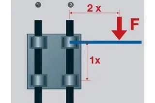
The 2:1 rule,
1. Floating bearing, 2. Fixed bearing
The 2:1 Rule
When using drylin® linear guides, it is important to ensure that the acting forces follow the 2:1 Rule (see drawing, right). If either the load or the drive force (F) is greater than twice the bearing length (1x), then a binding or interrupted motion may occur.
If the location of the drive force or load can not be changed, simply increase the distance between the bearings, or create a counterbalance to move the center-of-gravity back within the 2 to 1 ratio.
This principle applies regardless of the load or drive force. It is a product of friction and is always related to the fixed bearing. The greater the distance between the drive force and the guide rail, the higher the degree of wear and required drive force.
Failure to observe the 2:1 rule when using drylin® linear guides can result in uneven motion or other problems. Such situations can often be remedied with relatively simple modifications.
Fixed and floating bearing mounting instructions
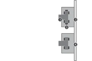
Lateral installation option with floating bearing in z-direction
When using systems with two parallel rails, one side must be designated as the “fixed” rail, and the opposite side as the “floating” rail.
Why use floating bearings?
- promotes smooth gliding performance and maximizes bearing life
- prevents binding caused by parallelism and misalignment errors
- decreases necessary drive force and wear by minimizing friction-forces
- enhances the precision of the system over the bearings’ lifetime
- reduces assembly time and cost
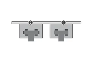
Horizontal installation option with floating bearing in z-direction
Fixed Bearings
The “fixed” bearing rail should be positioned closest to the driving force. This rail will determine the precision of the system; no system should contain more than two “fixed” bearings.
Floating/Self-Aligning Bearings
The “floating” rail should be the rail located furthest from the drive force. It should only act as a guide, and will compensate for misalignment or errors in the system ensuring proper functionality.
Mounting Surfaces
The mounting surfaces for rails and bearings should have a very flat surface (e.g. milled surface) in order to enhance performance. Variations in these surfaces may be compensated for by using floating bearings.
See the different installation variations (right).
1
Rail
2
Gliding elements
3
Fixed bearing carriage
4
Floating bearing carriage LLZ or LLY