Change Language :
Micro flizz® installation videos
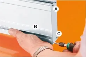
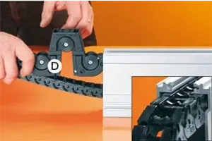
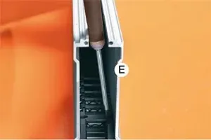
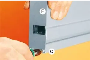
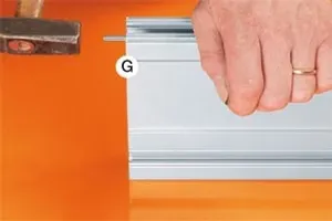
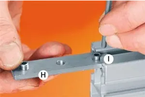
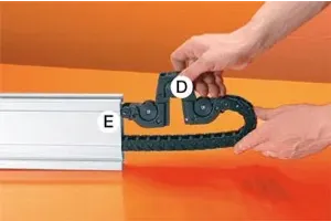
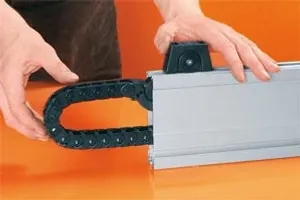
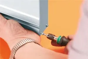
Assembling single rail with a carriage

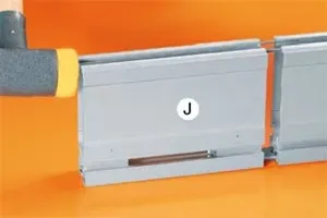
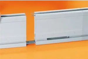
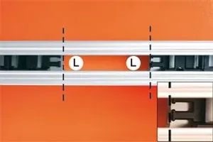
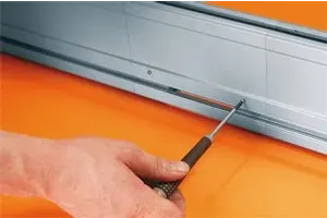
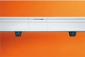
Assembling several channels with two carriages

Overview of Assembly Instructions for igus® e-chains®
Contact Us
Questions or product information? Please contact:

Customer Service
Customer Service:
Phone: Monday to Friday from 8 am - 5 pm
LiveChat: 24 hours
Book a Call
Book an Appointment with a Product Expert